VRRP 虚拟路由冗余协议
实验要求:
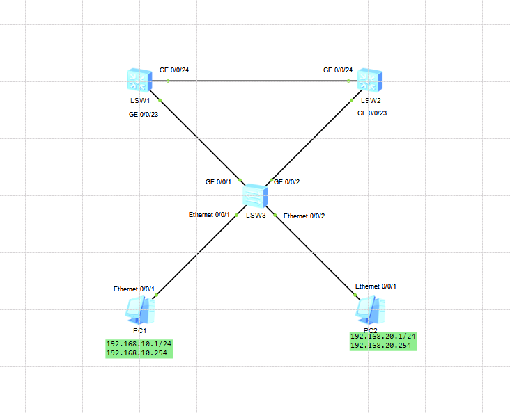
配置 VRRP,使 LSW1、LSW2 同时为 VLAN10、VLAN20 提供冗余网关
VLAN10:
虚拟网关:192.168.10.254
LSW1 为 Master,LSW2 为 Backup
VLAN20:
虚拟网关:192.168.20.254
LSW2 为 Master,LSW1 为 Backup
实现负载分担 + 双主互备:
LSW1: vlan10主,vlan20备
system-view
undo info-center enable
sysname LSW1
vlan batch 10 20

#基础端口配置
interface GigabitEthernet 0/0/23
 port link-type trunk
 port trunk allow-pass vlan all #允许所有vlan通过
interface GigabitEthernet 0/0/24
 port link-type trunk
 port trunk allow-pass vlan all #允许所有vlan通过
quit

#配置vlan接口ip
interface Vlanif 10
 ip address 192.168.10.252 255.255.255.0 #子网掩码可缩写为24
interface Vlanif 20
 ip address 192.168.20.252 255.255.255.0 #子网掩码可缩写为24

#vlan 10 VRRP主设备
nterface Vlanif 10
 vrrp vrid 10 virtual-ip 192.168.10.254
 vrrp vrid 10 priority 120
 vrrp vrid 10 preempt-mode timer delay 0  # 立即抢占
#vlan 20 VRRP备设备
interface Vlanif 20
 vrrp vrid 20 virtual-ip 192.168.20.254
 quit

#保存配置
quit
save
y
LSW2:
system-view
undo info-center enable
sysname LSW2
vlan batch 10 20

#基础端口配置
interface GigabitEthernet 0/0/23
 port link-type trunk
 port trunk allow-pass vlan all #允许所有vlan通过
interface GigabitEthernet 0/0/24
 port link-type trunk
 port trunk allow-pass vlan all #允许所有vlan通过
 quit
#配置vlan接口ip
interface Vlanif 10
 ip address 192.168.10.253 255.255.255.0
interface Vlanif 20
 ip address 192.168.20.253 255.255.255.0

#vlan 10 VRRP备设备
interface Vlanif 10
 vrrp vrid 10 virtual-ip 192.168.10.254
#vlan 20 VRRP主设备
interface Vlanif 20
 vrrp vrid 20 virtual-ip 192.168.20.254
 vrrp vrid 20 priority 120
 vrrp vrid 20 preempt-mode timer delay 0
 quit

#保存配置
quit
save
y
LSW3:
system-view
undo info-center enable
sysname LSW3
vlan batch 10 20

#基础端口配置
interface GigabitEthernet 0/0/1
 port link-type trunk
 port trunk allow-pass vlan all #允许所有vlan通过
interface GigabitEthernet 0/0/2
 port link-type trunk
 port trunk allow-pass vlan all #允许所有vlan通过
interface Ethernet 0/0/1
 port link-type access
 port default vlan 10
interface Ethernet 0/0/2
 port link-type access
 port default vlan 20
 quit

#保存配置
quit
save
y
PC配置:
PC1:
ip:192.168.10.1/24
网关:192.168.10.254
PC2:
ip:192.168.20.1/24
网关:192.168.20.254
验证与测试
在LSW1上输入:
display vrrp brief

#输出结果应为
VRID  State        Interface                Type     Virtual IP
----------------------------------------------------------------
10    Master       Vlanif10                 Normal   192.168.10.254
20    Backup       Vlanif20                 Normal   192.168.20.254
----------------------------------------------------------------
Total:2     Master:1     Backup:1     Non-active:0
在LSW2上输入:
display vrrp brief

#输出结果应为
VRID  State        Interface                Type     Virtual IP
----------------------------------------------------------------
10    Backup       Vlanif10                 Normal   192.168.10.254
20    Master       Vlanif20                 Normal   192.168.20.254
----------------------------------------------------------------
Total:2     Master:1     Backup:1     Non-active:0
使用PC1 长时间ping PC2
ping -t 192.168.20.1
模拟线路故障,关闭LSW1的上行接口,观察ping
看到ping只会丢1~2个数据包后恢复连通性